Design Essentials for Automotive Headlamp Reflector Injection Molds
Automotive headlamp reflectors (also called reflector
mirrors) are critical safety and decorative components. They prevent direct glare, direct light beams, and are
visible through the outer lens. The part is an appearance component with vacuum aluminized coating and large
decorative textures. Due to high operating temperatures and the need for precise light distribution, reflectors
are molded from BMC (bulk molding compound) — a thermoset material
with near-zero shrinkage, heat resistance, flame retardancy, and excellent creep resistance.
Traditionally, BMC reflectors were compression-molded,
which suffered from low efficiency, high scrap rates, and health risks due to manual material handling. Injection mould for car headlamp covers using BMC has become the
standard alternative, offering better repeatability and lower cycle times. This article presents the design
essentials and technical summary for a two‑cavity (left+right) BMC headlamp reflector mold, based on a real
production case.
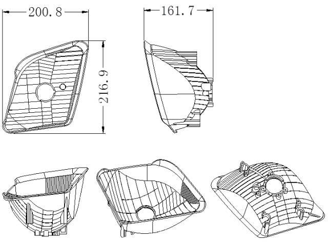
Fig.1 – Headlamp reflector
part (BMC material)
Part
dimensions: 216.9×200.8×161.7 mm
Material: BMC (thermoset, zero
shrinkage)
Key requirements:
- No gate marks, weld lines, sinks, or flash on cosmetic surface
- Draft angle ≥5° for vacuum aluminizing
- Complex freeform surfaces, no undercuts – part is left/right mirrored
- High light‑distribution accuracy (tolerance ±0.01–0.02 mm on reflective surfaces)
1. BMC Injection Molding Process
The chilled BMC compound is fed into a dedicated screw injection unit, where it is
melted at low barrel temperature (~25°C) through shear heating. The viscous material is then injected at high
pressure into a mold preheated to 140–160°C. Chemical cross‑linking occurs inside the hot cavity. After holding
and curing, the part is ejected. Compressed air is used to blow out any flash or debris before the next
cycle.
2. Structural Differences from Thermoplastic Molds
Although the basic construction resembles a conventional mold, BMC tooling has
distinct differences:
- Reversed mold (counter‑intuitive core/cavity layout): The convex reflector working surface
(which requires ultra‑low roughness and no ejector marks) is placed on the fixed half (core
side). The concave cavity is on the moving half. This is not an inverted mold – it is simply a
reversed arrangement. - Electric heating system instead of cooling: The injection barrel is water‑cooled, but the
mold itself is electrically heated (cartridge heaters). - Temperature‑controlled cold runners: The sprue bushing is water‑cooled to prevent premature
curing. A fan‑shaped gate (2.0–2.5 mm thick) on the moving side reduces shear heating and allows faster
filling. - Flash‑free parting line design: BMC has low viscosity; no holes, pockets, or lock blocks
are allowed on the parting line, otherwise flash becomes impossible to clean. - Aggressive venting and spillover grooves: Thermoset curing releases large amounts of
volatiles – vacuum assist and deep peripheral spillover grooves are used. - High precision and surface finish: Reflective facets cannot be hand‑polished – 5‑axis
high‑speed CNC (≥20,000 rpm) with special tools achieves 0.01–0.02 mm accuracy and 0.05–0.10 μm Ra.
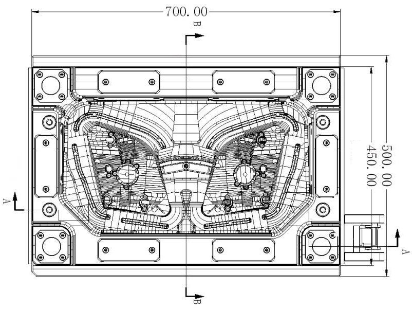
Fig.2 – General assembly of the 1+1
cavity BMC reflector mold
3. Critical Design Details
3.1 Heating System & Power
Calculation
Heating power W is calculated by:
W = G·cp·(Tm-To) /

        (3600·y·t)
Where G = total mold mass (kg), cp = specific heat of mold steel,
Tm = required mold temperature, To = room temperature, y = heater efficiency (0.3–0.5), t
= heating time (h).
Practical rule: 40–50 W per kg of mold weight. Cartridge heaters (Ø15.8 mm) are
placed 40–50 mm from the cavity surface, with 80–100 mm spacing. Phenolic insulation plates (8 mm thick)
surround the mold. Each heater group is controlled by a thermocouple positioned at the thermal center. For this
1 ton mold, the fixed half uses 2 vertical + 4 horizontal heaters per cavity; the moving half uses 3 vertical +
2 horizontal heaters per cavity.
3.2 Venting & Flash
Management
Because BMC generates large gas volume during cross‑linking, conventional parting
line vents are insufficient. This mold combines:
- Deep peripheral spillover grooves on the moving half, with ejector pins underneath to push out cured
overflow material. - Vacuum assist applied at the flow front ends of the fixed cavity.
- High‑temperature O‑rings at parting line and insert bottoms to enable effective vacuum sealing.
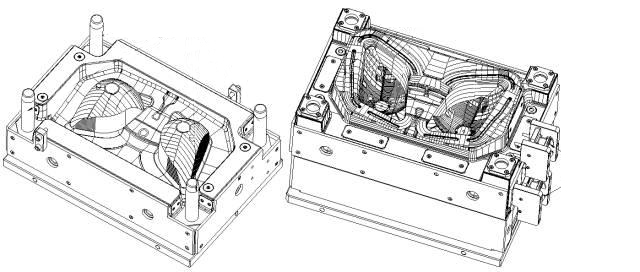
Fig.3 – Spillover grooves around the moving cavity with ejectors
3.3 Tool Steel Selection &
Parting Line
The fixed half (reflector core) requires excellent polishability and wear resistance
due to glass fiber content. Steel: 2344 ESR (hot work tool steel, vacuum remelted), hardened to
48–52 HRC, then hard chrome plated and polished. Moving half and inserts: 2344 HT, also
48–52 HRC.
Interlocks are designed with 7° minimum insertion angles, and 5°
wear plates are added on the fixed side to simplify spotting. The parting line surface is machined by high‑speed
CNC with ≤0.01 mm accuracy. All non‑forming corners have R≥5 mm to prevent stress cracking.
3.4 Ejection System
Due to BMC’s hardness and high shrinkage on cores, ejection requires large‑diameter
ejector pins (many pieces) distributed near ribs and areas with high wrapping force. Pins are grid‑knurled on
the face and rotation‑locked for odd‑shaped heads. The mold uses four return pins without springs – the
machine’s ejector plate is pulled back positively. Limit stops are placed above KO holes, and support pillars
cover 25–30% of the ejector plate area to prevent deflection.
3.5 Three‑Level Guidance
System
Automotive lighting molds require precise alignment to avoid flash and step
mismatch:
- Level 1: Four D40×225 round guide pillars (limited to 10× diameter) – primary positioning.
- Level 2: Four‑corner step interlocks and peripheral box‑lock with 5° angled wear plates.
- Level 3: Mold insert male/female locks (angled 0.5‑1° less than the smallest cavity angle)
to protect thin shutoffs.
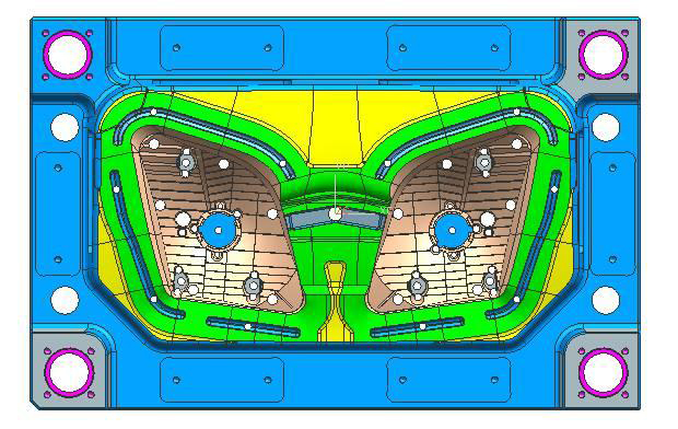
Fig.4 – Three‑level guidance system (guide pillars, peripheral
interlocks, and insert locks)
All insertion angles on the parting line are at least 7° to extend tool life and
prevent flash.
4. Mold Strength & Plate Thickness Guidelines
For automotive reflector molds without slides, the standard edge distance
A/B is calculated as: distance from cavity edge + 30–50 mm sealing land (small to large molds) +
50–70 mm relief area. In this 1+1 cavity mold, A1=A2=115.6 mm, with 73 mm between cavities. The minimum steel
thickness from deepest cavity to plate back is ≥80 mm (fixed half) and ≥100 mm (moving half due to empty space
between support blocks).
5. Mold Operation Sequence
- Melt injected into heated cavity, holding pressure applied, cured part solidifies.
- Mold opens at parting line (stroke 300 mm).
- Machine ejector cylinder pushes ejector plate (70 mm stroke), pins eject part and runner.
- Robot picks the part; compressed air blows flash from spillover grooves.
- Ejector plate retracted positively, mold closes – next cycle begins.
6. Design Checklist & Critical Lessons
- Draft angles: Minimum 5° for aluminized surfaces; 5–10° recommended where geometry allows.
- No sharp corners: All internal and external corners radiused to avoid cracking of hardened
steel. - Mirroring but not mirrored holes: Left/right reflector parts are mirrored except
the bulb holes and surface textures – those are translationally identical (bulb sockets are not left‑hand or
right‑hand). - Use a dedicated BMC injection machine with barrel cooling and high injection pressure
capability. - Ejector system must be balanced – large pin diameter, high pin density, otherwise part will
stick or crack.
Need a DFM review for your automotive lighting
project?
DTG TECH CO., LTD. specializes in complex injection mould for car headlamp
covers and reflectors. Our engineers provide moldability analysis, heating/venting simulation, and prototype
sampling from our ISO‑certified facility.
Why DTG for Automotive Reflector Molds
✓ Reversed mold design
High‑gloss reflector surface on fixed half – no ejector pins on optical
faces.
✓ Precision heating & control
Cartridge heaters with thermocouple feedback, uniform 140–160°C cavity
temperature, ±2°C stability.
✓ Vacuum + spillover venting
Eliminates gas burns and short shots without post‑trimming.
✓ High‑speed CNC finishing
5‑axis machining at 24,000 rpm achieves Ra 0.05μm, no hand polishing
needed.
✓ Wide material compatibility
Experience with BMC, phenolic, and other thermosets for automotive
lighting.
✓ Full documentation
Mold flow analysis, design for manufacturability reports, and CMM inspection
per PPAP level 3.
Read more: How to design injection
molds for automotive light covers | Transparent auto lamp housing mold case study | 2K car light components
As a
manufacturer of injection-moulded headlights and custom plastic injection molding for car fog light covers, DTG Tech
Co., Ltd. delivers production‑ready BMC molds validated by multiple top‑tier automotive lighting suppliers. From
prototype to mass production – our engineering team supports you at every stage.