Plastic Comb Injection Molding: From Comb Teeth DFM to Stable Production
Plastic comb injection molding looks straightforward until the geometry of the teeth is considered. A comb may be a single molded component, but dozens of long, narrow and closely spaced teeth create demanding conditions for material flow, mold machining, venting, cooling and ejection. Producing one acceptable sample is only part of the task; the manufacturing process must reproduce the same tooth geometry and overall part condition consistently.
At DTG, we approach a comb as an engineered injection-molded part rather than simply a flat plastic product. During DFM, mold development and trial molding, our engineering team considers how the body and teeth interact throughout the entire molding cycle. This guide explains the main design and process factors product designers should evaluate before moving an injection molded comb into repeatable production.
Why a Plastic Comb Is More Demanding Than It Looks
The main manufacturing challenge comes from the contrast between the comb body and its teeth. The body may be relatively broad and flat, while the teeth create multiple narrow, parallel flow paths. Tooth length, thickness, spacing, root geometry and the transition into the body all influence moldability.
Filling
Thin tooth sections increase flow resistance, while longer flow paths give the melt more opportunity to cool before reaching the tooth ends.
Tooling
Multiple parallel tooth cavities make machining accuracy, spacing, alignment, parting surfaces and local venting important to part consistency.
Cooling
The body and teeth do not necessarily cool and shrink in the same way, which can influence body flatness and tooth straightness.
Ejection
Even a correctly filled part can be deformed if release resistance and ejection forces are not considered during product and mold design.
DFM Comes Before the Plastic Comb Molding Process
A tooth profile that can be created in CAD is not automatically suitable for stable injection molding. From a manufacturing perspective, DFM must answer more than whether the mold can physically be manufactured. The more useful question is: can the teeth fill, cool and eject consistently in production?
When we review a custom comb design, relevant features include tooth length, thickness and width; tooth spacing and root geometry; wall transitions between the teeth and body; overall body thickness and flatness; draft; undercuts; and surfaces that may influence mold release.
There is no useful universal tooth thickness, spacing or draft value that applies to every comb. These decisions depend on the geometry, resin, appearance requirements and tooling strategy. Designers developing a new OEM product can also review our custom plastic comb injection molding project capabilities to understand how product requirements connect with DFM, tooling and production.
Material Preparation and Flow Behavior
Material preparation is more than feeding resin into a molding machine. The resin grade, applicable drying requirements, moisture condition, color or masterbatch preparation, contamination control and batch consistency can all influence the molding window.
For comb teeth, melt-flow behavior deserves particular attention. As molten resin enters a long, thin tooth cavity, it encounters greater resistance than it does in a larger cross-section. The material also loses heat as it travels. Resin behavior therefore interacts directly with tooth geometry, gate position, mold temperature and injection conditions.
PP, ABS and other candidate materials have different processing and shrinkage characteristics, so material selection should not be separated from product design. For a focused comparison, see our guide to PP, ABS and material selection for plastic combs.
Why Plastic Comb Mold Precision Matters
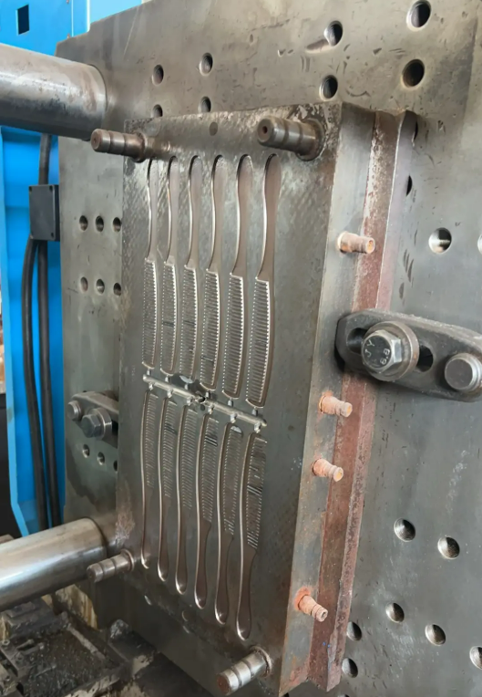
The geometry of the finished teeth originates in the comb injection mold. When many narrow cavities are arranged in parallel, tooling accuracy affects more than an isolated dimension. Tooth cavity dimensions, spacing, cavity/core alignment, insert fitting and parting-line condition can influence tooth thickness, pitch, straightness, appearance and release behavior.
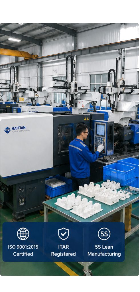
At our factory, mold manufacturing and injection molding are connected parts of the same development process. Depending on the mold structure and feature requirements, tooling may involve CNC machining, EDM and other appropriate mold-making operations, followed by fitting, polishing and dimensional verification. The required tolerances should be determined from the actual drawing and manufacturing requirements rather than assigned as a generic number.
Gate, Runner and Venting Design
Gate Location and Filling Direction
For a comb, the important gate question is not simply which gate type is available. It is how the selected melt-entry location influences the flow path into the body and multiple teeth. Gate position and size affect flow distance, pressure distribution, filling balance and the location of the gate vestige.
An unsuitable flow strategy can leave some regions with a longer or more restrictive path than others. That increases the risk that distant or difficult tooth features will not fill under the same conditions as features closer to the melt entry.
Runner Balance
The runner system must deliver melt with an appropriate balance of pressure loss, material distribution and process stability. This becomes especially important when a plastic comb mold contains multiple cavities. Producing one good cavity is different from maintaining consistent filling across all cavities in repeated cycles.
Venting at Tooth Ends
Venting is easy to overlook but particularly relevant to injection molding comb teeth. As plastic moves toward the end of a narrow tooth cavity, the air already occupying that space must escape. Trapped gas can contribute to incomplete filling or burn-related appearance defects. Vent locations therefore need to be considered in relation to the actual end-of-fill regions of the mold.
Injection Molding Comb Teeth: The Critical Filling Stage
Comb tooth filling is the combined result of part geometry, material behavior, mold design and process settings. This relationship is more useful than treating injection pressure or temperature as isolated parameters.
Thin tooth cross-section → higher flow resistance → melt loses heat while traveling → flow becomes more difficult toward the tooth end → risk of incomplete filling increases.
Variables such as resin flow behavior, melt and mold conditions, injection speed and pressure, gate geometry, venting, tooth thickness, tooth length and total flow distance interact. For this reason, our molding team establishes the process around the actual resin, mold and part rather than applying a fixed set of generic parameters.
Packing, Cooling and Shrinkage Control
Packing and Holding
After filling, packing and holding help compensate for material shrinkage while the part solidifies. A comb combines thin teeth with comparatively heavier body regions, so different sections may not respond identically. Excessive or insufficient packing can contribute to dimensional changes, residual stress, sink-related appearance issues or warpage depending on the geometry and resin.
Cooling Is a Dimensional Process
Cooling should not be viewed simply as waiting until the plastic becomes rigid enough to eject. Cooling-channel layout and temperature distribution affect shrinkage, residual stress, cycle stability and final geometry. For combs, two practical results are especially important: body flatness and tooth straightness.
Shrinkage and Tooth Spacing
The mold cavity defines the starting geometry, but the final injection molded comb is measured after the resin has cooled and contracted. Material shrinkage, local geometry and process conditions can therefore affect overall length, tooth pitch and alignment. Shrinkage allowance is incorporated into tooling, then the resulting dimensions are verified during mold trials rather than assumed from nominal material data alone.
Ejection: A Correctly Molded Comb Can Still Be Damaged
Once the part has filled and cooled, it still has to leave the mold without bending or damaging the teeth. Draft, surface condition, release resistance, ejector arrangement and part temperature at ejection all influence this stage.
Long, narrow teeth make this particularly relevant. If the molded part resists release, excessive ejection force can distort teeth or create stress marks even though filling was successful. This is why our DFM and mold-design review considers how the part will leave the mold at the same time as how it will be filled.
Common Plastic Comb Injection Molding Defects
Defects should be evaluated as symptoms of interactions between design, tooling, material and processing. The table below summarizes common observations and the areas normally investigated during troubleshooting.
| Defect | Typical Appearance on a Comb | Areas to Investigate |
|---|---|---|
| Short shot | One or more teeth are not completely formed, often toward difficult end-of-fill regions. | Flow behavior, gate restriction, venting, material and process conditions, tooth geometry and flow length. |
| Flash | Thin excess material at tooth edges, roots, the comb perimeter or parting line. | Mold fit, parting surfaces, mold condition, clamping and injection conditions. |
| Warpage | The comb body is curved or does not maintain the required flatness. | Cooling uniformity, shrinkage, wall distribution, residual stress and process stability. |
| Tooth deformation | Individual teeth bend or lose the intended straightness. | Cooling, ejection, release resistance, tooth geometry and material behavior. |
| Sink marks | Local surface depressions in heavier sections. | Wall thickness, local geometry, packing and cooling. |
| Burn marks | Darkened areas, particularly near difficult end-of-fill locations. | Trapped air, venting, filling behavior and process conditions. |
| Dimensional variation | Variation in tooth spacing, body dimensions or overall geometry. | Tooling accuracy, resin shrinkage, cavity consistency and process stability. |
Trimming, Finishing and Inspection
Molding complete does not necessarily mean the component is ready for approval. Gate vestiges, flash and appearance-critical surfaces may require trimming or finishing, while printing, logos or other secondary operations may apply to specific product designs.
Inspection should focus on characteristics that matter to the actual comb design. These can include overall length and width, body thickness, tooth length and thickness, tooth spacing, tooth straightness, body flatness, short shots, flash, warpage, surface condition, color consistency and gate condition. Logo or printing quality can also be included where applicable.
From Mold Trial to Repeatable Plastic Comb Manufacturing
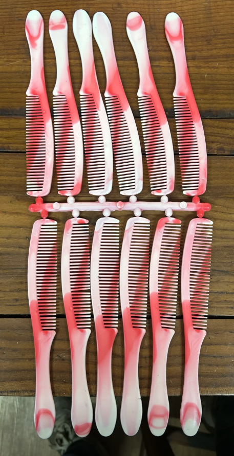
A mold trial is not simply a demonstration that plastic can enter the cavity. It is an engineering stage used to evaluate filling, tooth formation, dimensions, warpage, surface condition, gate appearance and ejection behavior. Findings can lead to mold or process adjustments followed by resampling and customer approval.
- Trial mold with the specified material and initial process window.
- Evaluate complete filling and individual tooth formation.
- Check relevant dimensions, tooth geometry and body flatness.
- Identify molding, tooling or ejection-related defects.
- Adjust the mold or molding process where required.
- Resample and confirm the resulting part condition.
- Move to production after sample approval, with appropriate batch quality control.
This progression is what turns a CAD model into a repeatable molded product. At DTG, our mold-making and injection molding services cover the development path from design evaluation and mold manufacturing through mold testing, modification, sample approval and production.
What Product Designers Should Resolve Before Tooling
For a new plastic comb project, resolving the following questions early can reduce unnecessary mold changes and shorten the path to a stable process:
- Are tooth length, thickness, spacing and root transitions practical for the selected material?
- Can the melt reach all critical tooth features without an unnecessarily difficult flow path?
- Where can the gate be placed without creating unacceptable appearance or filling problems?
- Where are the likely end-of-fill regions, and how will trapped air be vented?
- Can the body cool with acceptable flatness and dimensional stability?
- How will the part release and eject without bending the teeth?
- Which dimensions and appearance characteristics need to be verified during trial molding and production?
Single-Color and Two-Color Comb Projects
The manufacturing approach also changes when a design moves beyond conventional single-color molding. A two-color comb may be considered for visual differentiation, branding or a functional second material, but it introduces additional tooling, material compatibility and process considerations.
Designers evaluating this option can continue with our guide to two-color injection molding for custom plastic combs, which focuses on the additional decisions involved in multi-material or multi-color production.
Evaluate the Comb as a Complete Manufacturing System
The central lesson of the plastic comb manufacturing process is that no single molding parameter determines success. Tooth geometry affects flow; material behavior affects filling and shrinkage; mold precision affects spacing and repeatability; venting influences end-of-fill performance; cooling affects flatness and straightness; and ejection can determine whether a correctly molded part remains dimensionally acceptable.
For product designers, the most effective time to address these interactions is before tooling is finalized. If you have a comb CAD model, drawing, physical sample or reference product, our engineering team can review the design from a moldability and production perspective and discuss an appropriate tooling and molding approach.
Discuss DFM and Molding Requirements with DTG