How to Design Custom Handlebar Grips: Size, Hardness, Texture & Ergonomics
If you are developing custom handlebar grips for a bicycle, motorcycle or e-bike, it is tempting to start with the fun stuff — colour, logos and surface graphics. But that is not where a good grip design starts. The grip is the one part of the vehicle that sits directly between the rider and the handlebar, so small design decisions can have a surprisingly noticeable effect.
Get the inner diameter wrong and installation becomes a headache. Get the wall thickness or hardness wrong and the grip can feel either too harsh or too soft. Choose the wrong surface pattern and wet hands may not have enough traction. And if the ergonomic shape is poorly considered, a comfortable-looking grip can become tiring after a long ride.
From a product development perspective, we would normally work through the functional requirements first and leave appearance details until the basic fit and handling characteristics are under control.
1. Inner Diameter: Start With the Fit
The inner diameter is one of the first dimensions to lock down. It needs to match the actual handlebar or throttle tube, and “close enough” is not a particularly good strategy here.
Different vehicles use different handlebar dimensions. Bicycle applications can involve common bar diameters such as 25.4 mm and 31.8 mm, while some modern performance handlebars use larger diameters. Smaller bicycles, BMX products and certain folding-bike applications can use different dimensions again. Motorcycle applications commonly use a nominal 22 mm handlebar diameter, while bicycle components may use 22.2 mm in some applications.
That small difference matters. A motorcycle grip designed around a 22 mm bar should not automatically be treated as interchangeable with a component intended for a 22.2 mm bicycle bar.
For many flexible grips, the design relies on elastic deformation and an interference fit. The grip’s inner diameter is slightly smaller than the mating surface, allowing the material to stretch and hold the component in position. Other rigid controls and accessories may use clearance fits and mechanical fastening instead.
When we review a custom component, we would look at the actual mating dimensions, material behaviour, installation method and required retention before deciding on the final tolerance. The nominal diameter alone does not tell the whole story.
2. Grip Length: Make Sure the Hand Has Enough Room
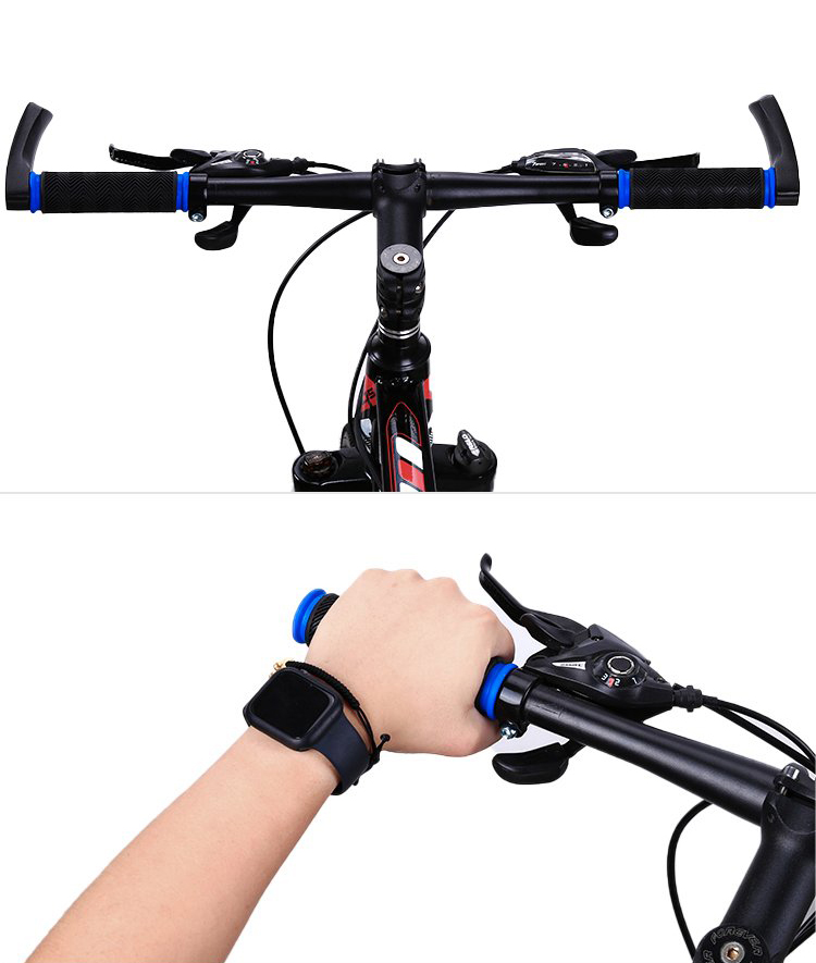
Grip length is not simply a case of “longer is better.” The usable length of the handlebar, hand size, brake position, shifter location and other controls all have to fit into the same space.
A grip that is too long can interfere with brake clamps, shifters or switch assemblies. A grip that is too short can leave part of the palm unsupported and increase pressure around the thumb and wrist during longer rides.
Motorcycle designs need another consideration: the throttle tube and switchgear occupy part of the available space. The grip therefore has to work with the complete control layout rather than being designed as an isolated rubber or elastomer sleeve.
For a custom design, it is useful to establish the net gripping area first. Once the available space is known, the grip length can be developed around the rider’s hand position and the surrounding controls.
3. Wall Thickness: More Material Does Not Automatically Mean More Comfort
Wall thickness affects cushioning, flexibility, grip feel and the amount of feedback transmitted from the handlebar to the rider’s hand. It is easy to assume that a thicker wall will always be more comfortable. In practice, the relationship is more complicated.
A soft material combined with a very thick section may deform too easily. That can make the grip feel vague rather than comfortable, especially when the rider needs precise control. A thinner section can provide a firmer response, but may transmit more vibration.
| Design Consideration | Thinner Section | Thicker Section |
|---|---|---|
| Grip feel | Generally firmer and more direct | Generally softer and more compliant |
| Vibration isolation | Less material available for cushioning | More potential for cushioning, depending on material |
| Control feedback | Often more immediate | Can become less precise if excessively soft |
| Manufacturing | Requires suitable filling and dimensional control | May require additional attention to shrinkage and deformation |
There is no universal wall thickness that works for every grip. A bicycle commuter grip, a mountain-bike grip and a heavy-duty control handle can have very different requirements. Material hardness, geometry and texture need to be considered together.
For custom molding, wall thickness also needs to be reviewed from a manufacturability perspective. Significant changes in section thickness can affect material flow, cooling and dimensional stability. That is why we prefer to review the geometry during design rather than trying to solve everything after the mold has already been made.
4. Shore Hardness: Find the Right Balance
Hardness is another specification that looks simple on a drawing but can produce very different results in the hand.
For flexible grip materials, Shore A is commonly relevant. The important point is to specify the hardness scale clearly. A number without its scale is incomplete information. “40 degrees,” for example, does not tell a manufacturer enough if the drawing does not state whether the specification is Shore A or another hardness scale.
The right hardness depends on the application. A comfort-oriented grip may need a softer formulation, while a control handle that requires precise feedback may need a firmer feel.
And here is the part that is easy to miss: hardness should not be considered independently from wall thickness. Two grips made from materials with the same nominal hardness can feel quite different if their geometry is different.
For that reason, prototype evaluation matters. A sensible development process can include checking the grip with a bare hand, with gloves and under wet-hand conditions where those scenarios are relevant to the final application.
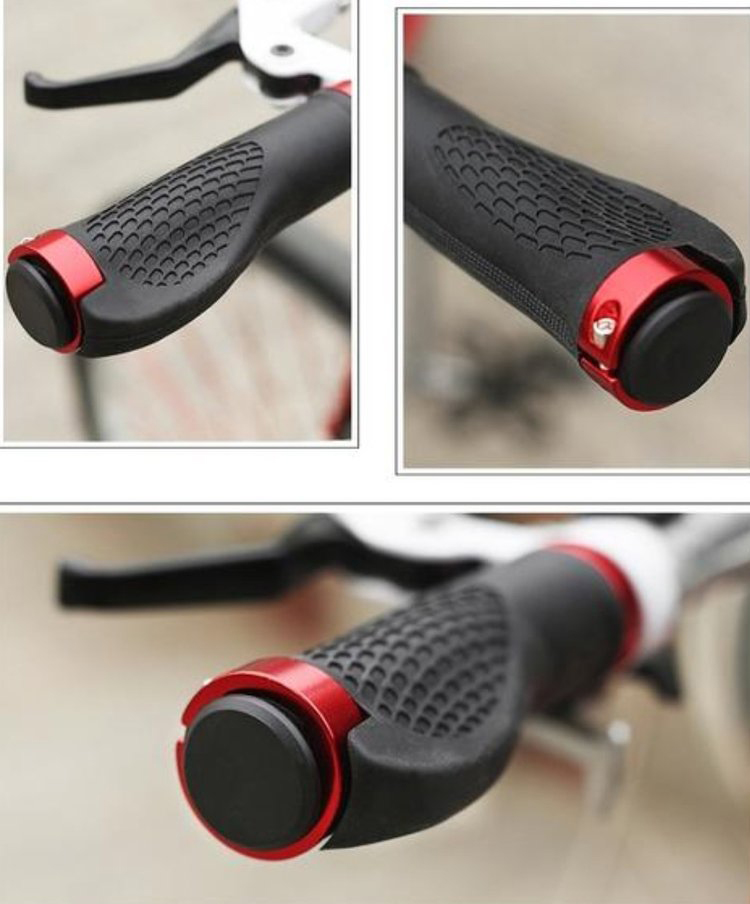
5. Surface Texture and Anti-Slip Patterns: Grip Comes First
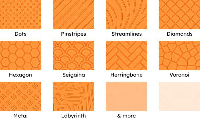
Surface texture is not just decoration. A raised dot pattern, rib, wave or waffle structure can change traction, pressure distribution, water evacuation and the way the grip feels under the hand.
There is a sweet spot. A pattern that is too shallow may lose its functional effect as the surface wears. A pattern that is too aggressive can create pressure points and become uncomfortable over longer periods.
When developing a molded grip, the texture should therefore be considered together with the material. A soft silicone-like material and a more abrasion-resistant rubber compound may use different surface geometries to achieve a similar functional target.
From a tooling perspective, texture also needs to be designed with the molding process in mind. Sharp transitions, extremely fine features and unsuitable draft conditions can create unnecessary manufacturing problems. Our engineering review would normally consider the intended surface geometry together with moldability and release requirements.
6. Ergonomic Shape: A Hand Is Not a Cylinder
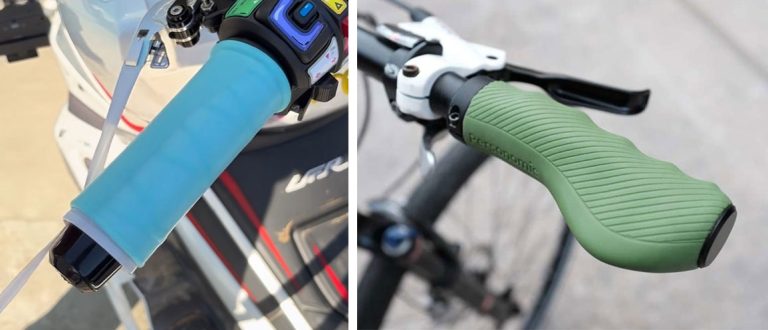
This is where grip design gets much more interesting. A human hand is not a round cylinder, so a straight tube is not necessarily the most comfortable solution.
Depending on the application, ergonomic features can include:
- Variable diameter sections
- Palm-support areas
- Wing-style profiles
- Controlled curvature
- Thumb recesses
- Defined finger contact zones
Different riding positions also change the requirements. Straight bicycle handlebars, swept-back bars and drop bars put the hand and wrist into different positions. Motorcycle grips have their own constraints because of throttle movement, switches and riding posture.
The basic goal is straightforward: the rider should be able to hold the grip naturally without excessive wrist deviation or concentrated pressure around the thumb joint and palm.
Good ergonomics also means thinking about movement and adjustment. If the grip or its associated components need to be positioned at a particular angle, the design should leave enough room for practical installation and adjustment.
7. Logo and Branding: Keep the Branding Out of the Way
A handlebar grip is a visible part of the finished vehicle, so branding can certainly be part of the design. But a logo should not create a hard spot in an area where the rider’s hand is constantly rubbing against it.
Logo placement is therefore worth considering alongside the ergonomic contact zones. Depending on the material and production method, branding may be achieved through molded-in features, engraving or printing. The appropriate method depends on the required appearance, durability and production process.
For molded components, integrating the branding into the part can offer a more durable result than relying entirely on a surface coating. During mold development, we can also review whether the logo geometry is suitable for the intended molding process.
8. Color: Appearance Still Has to Work With the Material
Colour is usually one of the easier design decisions, but it still needs to be considered from a manufacturing point of view.
Different elastomer and polymer systems have different colouring characteristics. Bright colours, translucent effects and stable appearance can depend heavily on the material formulation and processing method. A colour that looks good in a design file is not automatically identical to the final molded part.
For production, it is useful to define a clear colour reference and establish an approved sample before mass production. That gives both sides something physical to compare against rather than relying only on a screen image.
Environmental and regulatory requirements should also be treated separately from appearance. If a grip is intended for a particular export market, the required material declarations and compliance documentation should be established during product development rather than left until shipment.
9. Tolerance and Fit: The Details That Decide Whether the Part Actually Works
Once the major dimensions are established, tolerances need to be added to the drawing. This is where a custom grip moves from a concept into a manufacturable component.
The drawing should clearly define the important interfaces, including inner diameter, outer diameter, overall length, wall thickness and any critical geometric features. Surface texture depth, logo position and colour requirements should also be documented where they affect the finished product.
For flexible grips, the fit cannot be judged by nominal diameter alone. Material elasticity, shrinkage, wall thickness and the actual mating surface all influence installation and retention.
We therefore recommend treating the mating interface as a system. If the grip is being designed around an existing handlebar or throttle tube, the actual component dimensions should be used as a design input wherever possible.
10. What Should Be on the Drawing?
If you are sending a custom handlebar grip to a manufacturer, a good drawing should remove as much ambiguity as possible.
| Specification | What to Define |
|---|---|
| Inner diameter | Mating diameter and required fit |
| Grip length | Usable gripping area and control clearance |
| Wall thickness | Nominal section and critical tolerance areas |
| Hardness | Material hardness scale and target value |
| Surface texture | Pattern, depth and functional contact areas |
| Ergonomic profile | Palm support, taper, recesses and contact geometry |
| Colour | Reference colour and approved sample |
| Branding | Logo artwork, location, size and production method |
| Tolerance | Critical dimensional and fit requirements |
11. A Practical Development Sequence for Custom Grips
When the project is still at the design stage, there is a simple way to avoid making the process unnecessarily complicated.
- Define the mating component. Confirm the handlebar, throttle tube or control diameter.
- Define the usable grip area. Check available length and clearance around controls.
- Choose the material family. Consider environment, flexibility, abrasion and required feel.
- Set the wall thickness. Balance cushioning, feedback and manufacturability.
- Select hardness. Specify the hardness scale and target range clearly.
- Develop the surface texture. Match the traction pattern to the material and use conditions.
- Develop the ergonomic profile. Consider hand position, pressure distribution and riding posture.
- Add branding and colour. Finalise appearance after the functional geometry is stable.
- Review tolerances and tooling. Check whether the geometry can be molded consistently.
- Prototype and evaluate. Check fit, installation, grip feel and relevant environmental conditions before committing to production.
This sequence also makes communication with a manufacturer much easier. Instead of sending a drawing that says “make this grip softer,” you can provide the actual dimensions, hardness target, surface requirements, fit conditions and intended application.
12. How DTG Can Support the Mold Development Stage
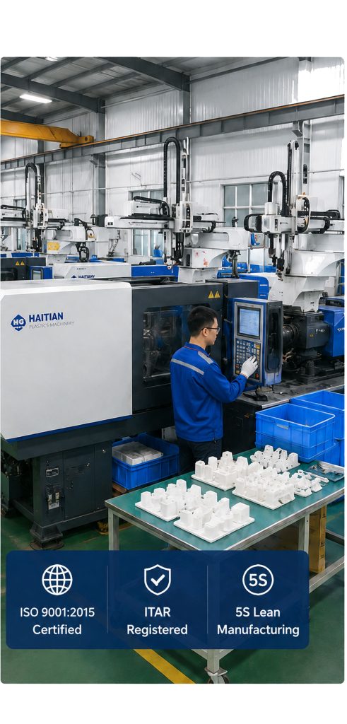
For custom molded components, the transition from product concept to production tooling is where engineering review becomes particularly useful. At DTG, our core manufacturing capabilities cover mold design and mold manufacturing, as well as plastic injection molding and related custom manufacturing processes.
For a new grip or similar molded component, the useful starting point is the product information itself: a 2D drawing, 3D CAD file, dimensions, photos of the mating component, material requirements and intended application. From there, the geometry can be reviewed for manufacturability before tooling decisions are finalised.
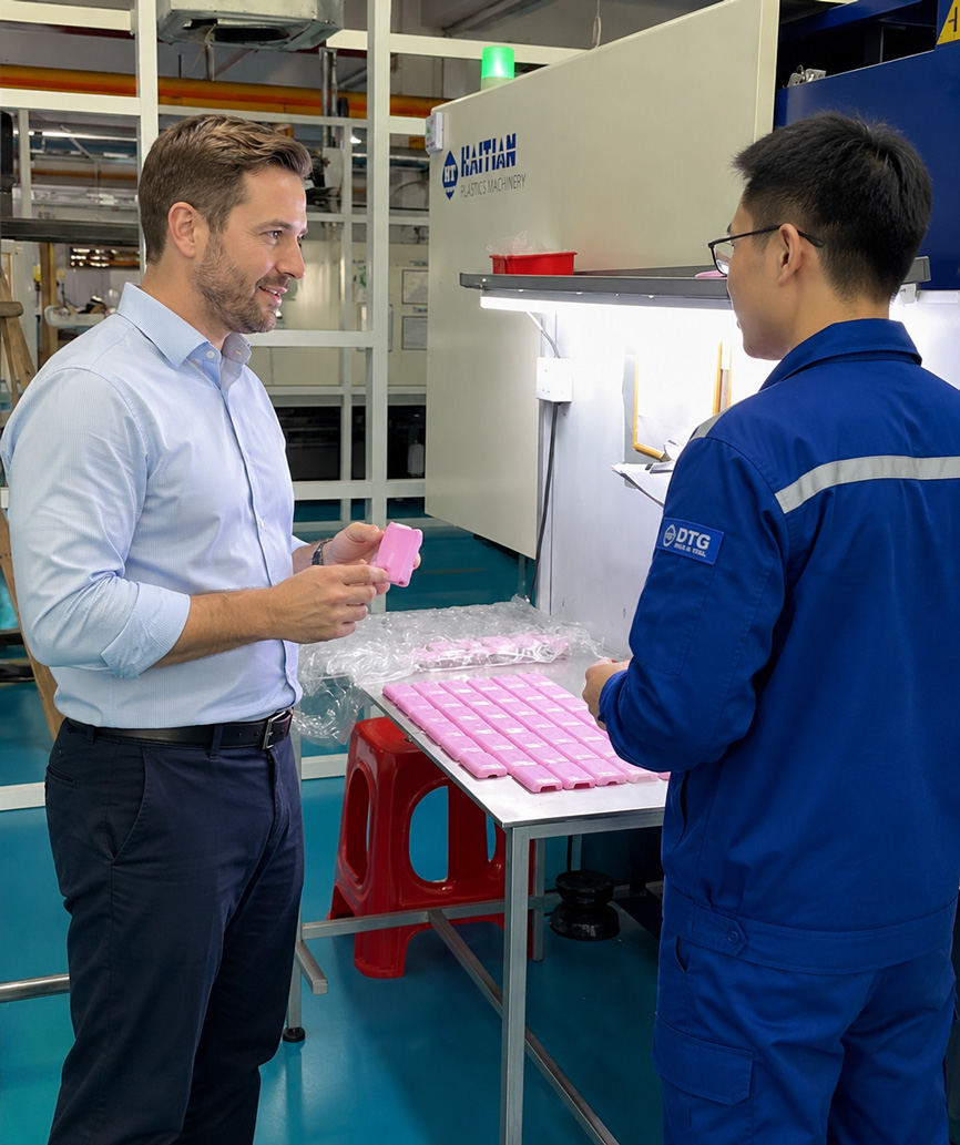
If your design is still being worked out, that is fine too. A clear discussion about the handlebar interface, grip length, wall thickness, hardness, texture and ergonomic requirements can often identify problems before they become tooling problems.
Have a custom grip
concept in development?
Send us the drawing, CAD file or even a clear product reference with
the key dimensions. Our engineering team can review the mold-development requirements and discuss the next step
for a custom manufacturing project.
Contact DTG about your custom component project
Final Thoughts
There is no single “correct” handlebar grip specification. The right design depends on the mating diameter, available space, material, hardness, wall thickness, surface texture, ergonomics and the environment in which the product will be used.
The practical approach is to get the fundamentals right first: fit, length, wall thickness and material. Then refine hardness, texture and ergonomic shape. Once the functional design is stable, lock down tolerances, colour and branding before moving into tooling.
A grip may be a relatively small molded component, but it has a direct effect on how the finished product feels in the user’s hands. Good design is therefore less about adding more features and more about getting the important details right.