Designing a mold for plastic injection molding involves several critical steps to ensure the final part meets specifications and is produced efficiently. Here’s a comprehensive guide to designing a mold for plastic injection:
1. Understand the Part Requirements
- Material Selection: Choose the appropriate plastic material based on the part’s functional requirements, including strength, flexibility, and thermal properties.
- Part Geometry: Analyze the part design for complexity, undercuts, wall thickness, and any intricate features.
- Tolerance and Finish: Define the required tolerances and surface finish quality for the part.
2. Design Considerations for the Mold
1. Mold Layout
Single vs. Multi-cavity:
- Single-cavity molds produce one part per cycle and are typically used for low-volume production.
- Multi-cavity molds produce multiple parts per cycle, increasing production efficiency for high-volume manufacturing.
Family Molds:
- A family mold produces different parts in a single mold, useful for assemblies requiring multiple components.
2. Parting Line

Location:
- Choose a parting line that minimizes visible seam lines and ensures ease of ejection.
- Typically located along the part’s edges or areas that do not affect aesthetics or function.
Types:
- Straight parting lines are simpler to machine.
- Complex parting lines may be required for intricate part geometries.

Choose us for your custom injection molding needs and experience excellence in every detail. Our China-based factory provides innovative solutions, competitive pricing, and fast turnaround times. Get your custom quote now!
3. Draft Angles
Purpose:
- Draft angles facilitate the removal of the part from the mold.
- Typically, a draft angle of 1-2 degrees is standard, but it may vary based on part geometry and material.
Application:
- Apply draft angles to all vertical surfaces relative to the mold opening direction.
4. Wall Thickness

Uniformity:
- Maintain uniform wall thickness to ensure consistent cooling and reduce defects.
- Avoid sharp changes in wall thickness to prevent sink marks and warping.
Guidelines:
- Common wall thickness ranges from 1.5mm to 3mm, depending on material and part design.
5. Ribs and Gussets
Purpose:
- Add ribs and gussets to enhance part strength and rigidity without increasing wall thickness.
- Design ribs with appropriate thickness (about 60% of the main wall thickness) to avoid sink marks.
6. Undercuts
Design Around Undercuts:
- Minimize or eliminate undercuts to simplify mold design and reduce tooling costs.
- If unavoidable, use side actions or lifters to mold parts with undercuts.
3. Cooling System

Design Efficient Cooling Channels:
- Incorporate cooling channels close to the mold cavity to ensure uniform cooling.
- Use conformal cooling channels for complex geometries to improve cooling efficiency.
Material Selection:
- Use materials with high thermal conductivity, such as copper alloys, for cooling channels.
4. Gating System
Gate Location:
- Position gates to ensure balanced filling and minimize weld lines and air traps.
- Common gate types include edge gates, pin gates, and submarine gates.
Gate Size:
- Design gates to allow for smooth flow of molten plastic and proper packing pressure.
5. Venting
Incorporate Vents:
- Place vents at the end of flow paths and in areas where air might get trapped.
- Typical vent depth is around 0.02mm to 0.05mm, depending on the material.

As a leading mold injection manufacturer in China, we deliver superior molds for various industries. Our state-of-the-art facilities and expert team ensure top-notch quality and timely delivery. Contact us now for a competitive quote!
6. Ejection System
Ejector Pins:
- Strategically place ejector pins to avoid part damage and ensure smooth ejection.
- Ensure even distribution of ejector pins to prevent warping.
Ejector Plates:
- Use ejector plates to push parts out of the mold, especially for complex parts.
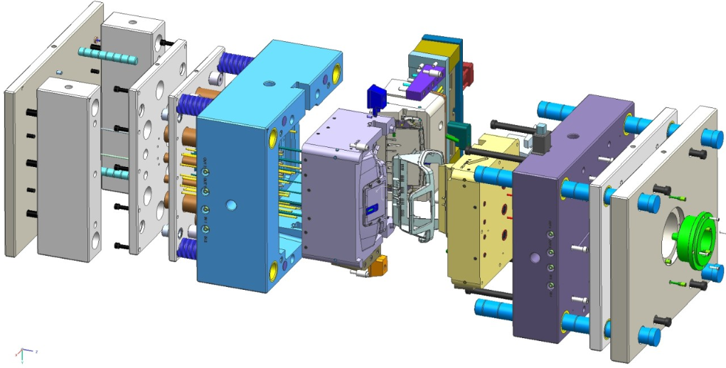
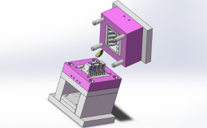
7. Mold Base and Components
Mold Base:
- Select a standard mold base size to reduce costs and simplify machining.
- Consider using pre-hardened mold bases for durability.
Components:
- Include leader pins, bushings, and alignment locks to ensure proper alignment and function.
8. Simulation and Testing
Mold Flow Analysis:
- Use mold flow analysis software to simulate the injection molding process.
- Identify potential issues like weld lines, air traps, and uneven cooling.
Prototyping:
- Create prototype molds for testing and validation before full-scale production.
Summary of Steps
- Understand the Part Requirements
- Design Considerations for the Mold
- Mold Layout (Single vs. Multi-cavity)
- Parting Line
- Draft Angles
- Wall Thickness
- Ribs and Gussets
- Undercuts
- Cooling System Design
- Gating System Design
- Venting
- Ejection System Design
- Mold Base and Components
- Simulation and Testing
Conclusion
Designing a mold for plastic injection molding requires careful consideration of part requirements, mold layout, cooling systems, gating, venting, and ejection systems. By following these guidelines and using simulation tools, you can create efficient and effective mold designs that ensure high-quality production and long mold life.
Related Conten: Mold Design / Mold Manufacturing

