Creating a plastic injection mold in SolidWorks involves several steps, including part design, mold design, and the creation of core and cavity blocks. Below is a step-by-step guide to help you through the process:
Step 1: Design the Part
- Open SolidWorks: Start by opening SolidWorks and creating a new part file.
- Design Your Part: Use SolidWorks’ modeling tools to design the plastic part you want to mold. Pay attention to design for manufacturability principles such as draft angles, uniform wall thickness, and avoiding sharp corners.
Step 2: Prepare the Part for Molding
- Check Draft Analysis: Ensure your part has the necessary draft angles for easy ejection from the mold. Use the Draft Analysis tool under the
Evaluatetab. - Add Parting Line: Determine where the parting line (the line where the two halves of the mold meet) will be. This is usually done manually based on the geometry of your part.
Step 3: Create the Mold Base
- Insert Mold Base: Go to the
Toolboxand insert a standard mold base that fits your part dimensions. Customize it as necessary. - Define Parting Line: Use the
Mold Toolstab and selectParting Line. SolidWorks will suggest a parting line based on your part’s geometry. Adjust as necessary.
[elementor-template id=”4330″]
Step 4: Create Parting Surfaces
- Parting Surfaces: Use the
Parting Surfacetool under theMold Toolstab to create surfaces that will define the separation between the core and cavity. These surfaces will extend from the parting line. - Shut-off Surfaces: Create shut-off surfaces for any holes or features that will require it. Use the
Shut-off Surfacestool in theMold Toolstab.
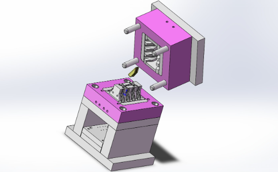
Step 5: Create Core and Cavity
- Tooling Split: Use the
Tooling Splitfeature in theMold Toolstab to split the mold into the core and cavity. This tool will use the parting surfaces and the mold base to generate the core and cavity blocks. - Core and Cavity Blocks: SolidWorks will generate the core and cavity blocks as separate bodies. Ensure these are properly aligned and fit together.
Step 6: Add Cooling Channels and Ejector Pins
- Cooling Channels: Design and add cooling channels to your mold to ensure the plastic part cools uniformly and efficiently. This can be done by sketching and extruding features within the mold base.
- Ejector Pins: Determine the placement of ejector pins to facilitate the removal of the part from the mold. Use the
Library Featurein theDesign Librarytab to insert standard ejector pins.
Step 7: Finalize the Mold Design
- Assembly: Insert the core and cavity blocks into the mold base assembly. Make sure everything is properly aligned and that there are no interferences.
- Interference Check: Run an interference check to ensure that there are no overlaps or gaps between the core, cavity, and mold base components.
Step 8: Create Drawings and Documentation
- Create Detailed Drawings: Generate detailed drawings for each component of the mold. These should include dimensions, tolerances, and any other necessary manufacturing information.
- BOM and Exploded Views: Create a Bill of Materials (BOM) and exploded views if necessary for assembly instructions.
[elementor-template id=”4331″]
Tips for Effective Mold Design
- Draft Angles: Ensure all vertical surfaces have a draft angle to facilitate part ejection.
- Uniform Wall Thickness: Maintain uniform wall thickness to avoid warping and ensure consistent cooling.
- Radii and Fillets: Avoid sharp corners by adding radii and fillets to reduce stress concentrations and improve material flow.
- Material Shrinkage: Account for material shrinkage in your design to ensure final part dimensions are accurate.
By following these steps, you can create a precise and functional plastic injection mold in SolidWorks.
Related Conten: Custom Plastic Extrusions
 DTG Mould Trade Process |
|
| Quote: | According to sample, drawing and specific requirement. |
|---|---|
| Discussion | Mold material, cavity number, price, runner, payment, etc. |
| S/C Signature | Approval for all the items. |
| Advance | Pay 50% by T/T |
| Product Design Checking | We check the product design. If some position is not perfect, or can not be done on the mould, we will send customer the report. |
| Mold Processing | Send report to customer once each week |
| Mold Testing | Send trial samples and try-out report to customer for confirmation |
| Mold Modification | According to customer’s feedback. |
| Balance Settlement | 50% by T/T after the customer approved the trial sample and mould quality. |
| Delivery | Delivery by sea or air. The forwarder can be designated by your side. |
 |
|