Multi-Material Injection Molding Knowledge Base
Two-Shot Injection
Molding vs Overmolding: A Practical Design and Tooling Guide
Understanding two-shot injection
molding vs overmolding is essential when designing a component that combines two colors, two
polymers, or a rigid substrate with a soft-touch surface. Although the finished parts may look similar, the
tooling architecture, equipment requirements, production sequence, material behavior, and cost structure are
fundamentally different.
At our factory, we regularly review projects in which the two processes are treated
as interchangeable during the early design stage. That assumption can create avoidable problems later,
including unsuitable material pairings, unstable insert positioning, excessive tooling complexity, visible
interface lines, weak bonding, and an uneconomical production plan.
This guide explains the difference between two-shot injection molding and overmolding from
a product designer’s perspective. It focuses on the practical decisions that affect manufacturability,
dimensional stability, surface quality, bonding reliability, cycle time, and long-term production
consistency.
What Is the Difference Between Two-Shot Injection Molding and Overmolding?
Two-Shot Injection Molding
Two-shot molding, also called two-component or dual-shot molding, forms two
materials sequentially in the same molding cycle. The first material is injected, the mold or core
changes position, and the second material is injected before the finished component is ejected. A
dedicated two-shot injection molding machine and a coordinated multi-material mold are normally
required.
Overmolding
Overmolding is a staged process. A rigid plastic, flexible part, or metal substrate
is manufactured first and removed from its original tool. The substrate is then transferred manually
or automatically into a second mold, where another material is molded over selected areas. Standard
single-shot molding machines can usually be used.
| Selection Factor | Two-Shot Molding | Overmolding |
|---|---|---|
| Production sequence | Two injections within one automated molding cycle |
Substrate molding followed by transfer and a separate molding operation |
| Typical tooling | One coordinated multi-material mold | Usually two independent molds or one mold plus purchased inserts |
| Machine requirement | Dedicated machine with two injection units | Conventional single-shot equipment is often sufficient |
| Insert positioning risk | Low when the first shot remains accurately located in the tool |
Higher because the substrate must be transferred and restrained |
| Production fit | Stable, repeatable, higher-volume programs | Lower or variable volumes, multiple substrate types, and flexible manufacturing |
In practical
terms: two-shot molding integrates both materials in one automated cycle, while overmolding
combines separately handled production stages.
Two-Shot Mold Design Considerations
A two-shot mold can use several transfer mechanisms. Selecting a more complex
structure than the product requires increases tooling cost, lead time, maintenance needs, and qualification
risk without necessarily improving the part.
Rotary-Platen Mold
The rotary-platen design is the most widely used arrangement. After the first shot,
the mold half rotates—commonly by 180 degrees—to align the first-shot component with the second injection
station. It provides stable transfer, efficient automation, and repeatable positioning for many housings,
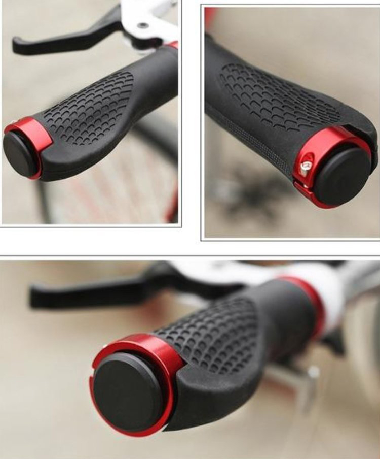
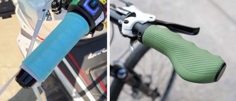
handles, grips, buttons, and cosmetic components.
Rotating-Core Mold
In a rotating-core system, the mold remains in position while a core rotates or
indexes between stations. This can provide precise control for compact components or geometries that cannot
be transferred effectively with a conventional platen rotation. The mechanism is more complex, however, so
it should be selected only when the geometry or tolerance requirement justifies it.
Sliding-Core or Cavity-Change Mold
A sliding mechanism changes the available cavity space between shots. This solution
can accommodate asymmetric interfaces or localized second-shot features, but wear, alignment, sealing, and
maintenance must be considered carefully.
Injection-Compression Arrangement
Injection-compression structures are used less frequently and are generally reserved for
specialized applications. They require close control of mold movement, material flow, pressure, and cavity
sealing.
Our design approach: begin with the simplest transfer method that can
reliably produce the geometry. For many products, a rotary-platen structure is the appropriate baseline. A
rotating core or sliding system should solve a defined product constraint rather than serve as a default
specification.
Managing Shrinkage and Dimensional Stability
Shrinkage cannot be evaluated independently for each material. The first
shot establishes the physical substrate for the second cavity, while the heat and pressure of the
second injection can further influence the first-shot dimensions.
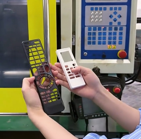
In one remote-control housing project, the first material was ABS with an
estimated shrinkage of 0.55%, and the second was TPU with an estimated shrinkage of 1.2%. When the
two cavity dimensions were calculated independently from theoretical values, the soft section was
approximately 0.38 mm shorter than the rigid section during the initial trial.
The correction was to establish the actual molded dimensions of the first shot and
then develop the second-shot cavity around that measured condition. This is more reliable than
treating the two polymers as unrelated single-material parts.
| Shrinkage-Related Risk | Possible Result | Recommended Design Response |
|---|---|---|
| Different material shrinkage behavior | Step mismatch, warpage, exposed edges, or assembly interference |
Reference second-shot steel dimensions to actual first-shot samples |
| Second-shot thermal loading | Reheating, distortion, or movement of the first material |
Review melt temperature, mold temperature, support conditions, and cycle timing |
| Excessive soft-material thickness | Sink, uneven cooling, internal stress, or dimensional drift |
Use controlled, reasonably uniform overmold thickness |
A larger mismatch in shrinkage or thermal expansion increases development risk.
Material data sheets are useful for initial calculations, but trial data should guide final steel
adjustments.
Material Bonding and Mechanical Retention
The functional value of a multi-material part depends on the interface remaining
secure throughout molding, assembly, transport, and service. Bonding performance is influenced by material
compatibility, surface condition, mechanical interlock, flow behavior, and processing conditions.
- Confirm chemical compatibility. Some TPU or TPE grades bond
effectively to selected ABS or PC grades, while low-surface-energy polymers such as PP often require a
specially formulated overmolding grade, surface treatment, or substantial mechanical retention.
Compatibility should be confirmed with the material supplier rather than assumed from the polymer family
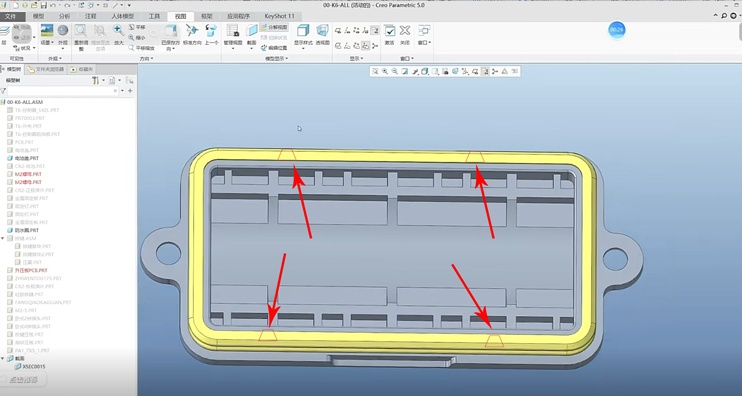
name. - Add mechanical interlocks where needed. Holes, slots,
grooves, undercuts, ribs, and wraparound features allow the second material to form physical anchors.
These features can improve retention when chemical adhesion is limited or when the component will
experience peeling and torsional loads. - Control the second-shot temperature and delay. The
first-shot surface must be in a condition that supports bonding. A second shot that is too cool, or a
long delay that allows the substrate surface to cool excessively, can reduce molecular interaction. - Design the gate and flow path for interface quality. The melt should reach critical
bonding areas with sufficient temperature and pressure. Long flow distances and thin sections may leave
the end of fill with weaker adhesion than the region near the gate.
Design Against
Peeling, Not Only Pulling
A material pair may resist direct tension but separate easily when an
exposed edge is peeled. Product designers should minimize accessible soft-material edges, avoid
abrupt termination points, and use geometry that wraps the flexible material around the rigid
substrate.
For grips, seals, protective covers, and soft-touch controls, the interface should
be evaluated under loads that reflect actual use. Peel, twist, compression, and environmental
exposure may be more relevant than a simple pull test.
Gate Location, Weld Lines, and Filling Behavior
Two-shot tooling includes two material-delivery systems, and the second gate must
work around the geometry already formed by the first shot. Gate selection therefore affects more than
filling. It also influences visible weld lines, bonding at the end of fill, air entrapment, soft-material
orientation, and interface flash.
In one appliance housing project, the second-shot gate created a weld line across a
primary cosmetic surface. Process changes improved the appearance but could not eliminate the underlying
flow pattern. A filling simulation later showed that the selected gate location directed two flow fronts to
meet in the visible region.
This type of problem is easier to prevent during DFM than to correct after steel has
been cut. Flow simulation is especially valuable when the second material travels around a perimeter, splits
around openings, fills thin soft-touch regions, or must maintain reliable bonding at a distant flow end.
Gate-Design Questions to Resolve Before Tool
Release
- Will a weld line appear on a customer-facing surface?
- Can the second material reach the final bonding area before excessive
cooling? - Is venting available at the end of fill?
- Can injection pressure move or deform the first-shot substrate?
- Can the gate vestige be hidden without compromising flow balance?
Texture Matching and Cosmetic Interfaces
Matching texture across rigid and flexible materials is difficult because the same
mold-surface pattern can appear different after molding. Steel grade, etching response, polymer gloss,
shrinkage, material hardness, and flow orientation all affect the final appearance.
A texture that is crisp on rigid ABS may look stretched or muted on a soft TPU or
TPE region. When two cavity inserts use different mold steels, chemical etching can also create variations
in texture depth unless the texture supplier compensates for the steel response.
For many products, the most robust strategy is to place the defined cosmetic texture on the
rigid surface and specify a matte or controlled low-gloss finish on the soft region. When texture continuity
is essential, we recommend validating the molded surface before final texturing the production tool.
Parting Lines, Shutoffs, and Material Transitions
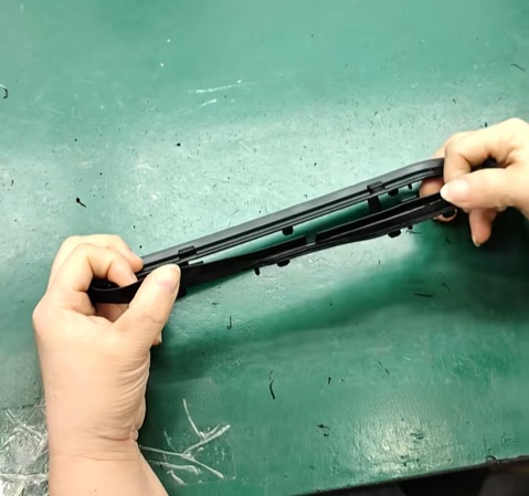
The boundary between rigid and flexible materials should be treated as an
engineered feature rather than a simple visual line. Shrinkage differences, shutoff condition, steel
alignment, and second-shot pressure can create flash, a visible height mismatch, or an irregular
edge.
A small step, recess, styling groove, or intentional reveal can conceal
minor variation and make the transition look controlled. For sealing or grip applications, the soft
material may be designed slightly proud of the rigid surface so that it compresses during
assembly.
Very small radii at the material boundary can be difficult to seal and may
encourage jetting or feather-like flash. The shutoff geometry should provide adequate steel support
and avoid fragile knife edges.
When to Use Overmolding Instead of Two-Shot Molding
The appropriate process depends on product geometry, materials, annual demand,
automation requirements, tooling budget, and supply-chain flexibility. Two-shot molding is not automatically
the more advanced or economical solution.
| Project Condition | Process Usually Favored | Reason |
|---|---|---|
| High and stable production volume | Two-shot molding | Automated transfer and elimination of a separate loading operation can reduce unit labor and improve consistency |
| Low or uncertain initial volume | Overmolding | Lower equipment dependency and a more flexible production setup may reduce initial program risk |
| Metal, cable, electronics, or purchased substrate |
Overmolding | The insert is produced outside the molding cycle and loaded into the overmold tool |
| Precise registration between two molded materials |
Two-shot molding | The first shot remains controlled by the mold rather than being reloaded as a loose insert |
| Multiple substrate variants sharing one soft layer |
Overmolding | Separate substrate supply can provide greater production and tooling flexibility |
| Integrated color, transparent window, or cosmetic feature |
Two-shot molding | Controlled registration and a single automated cycle support repeatable appearance |
Tooling for two-shot molding is typically more complex than a comparable
single-material mold, but the process can eliminate secondary assembly. The economic crossover cannot be
determined from volume alone; it should be calculated using tooling investment, cycle time, labor, scrap,
automation, maintenance, and expected program life.
For an overview of our production capabilities, visit our Two
Shot Molding Services page.
Recommended Wall Thickness and Shot Sequence
Wall thickness should be determined from the selected resin, flow length, part size,
geometry, and performance requirements. As an initial design reference, rigid sections are often developed
in the approximate range of 1.5–3.0 mm, while soft overmolded regions may begin around 1.0–2.0 mm.
Soft layers below approximately 0.8 mm may be difficult to fill over long flow
distances. Sections above approximately 3 mm can increase cooling time and create greater shrinkage
variation. These values are starting points, not universal limits, and should be verified through material
data, flow analysis, and mold trials.
Common Shot-Sequence Guidelines
- Mold the rigid substrate before the soft-touch material.
- Mold transparent material before an opaque second material when the geometry
supports that sequence. - Process the higher-temperature material first when the second material and
substrate can tolerate the selected conditions. - Use robust shutoff surfaces and avoid delicate steel conditions at the interface.
Common Defects and DFM Responses
| Defect | Likely Causes | DFM or Process Response |
|---|---|---|
| Delamination | Material incompatibility, low melt temperature, contamination, insufficient interlock, or excessive flow distance |
Confirm resin pairing, add retention features, protect substrate surfaces, and review gate location |
| Dimensional mismatch | Different shrinkage, first-shot distortion, or inaccurate cavity compensation |
Measure first-shot parts and adjust the second-shot cavity from actual trial data |
| Interface flash | Weak shutoff, insufficient support, mold mismatch, or excessive injection pressure |
Improve shutoff geometry, support the substrate, and optimize filling pressure |
| Short shot | Soft layer too thin, long flow path, low temperature, poor venting, or undersized gate |
Rebalance thickness, revise gate and venting, and review process conditions |
| Visible weld line | Flow fronts meet on a cosmetic area or at reduced temperature |
Relocate the gate, alter flow routing, improve venting, or incorporate an intentional styling feature |
| Air trap or burn mark | Enclosed flow region, inadequate venting, or excessive injection speed |
Add vents or overflow features and optimize the filling profile |
Validate Function Before Final
Cosmetic Processing
For a new two-shot tool, our preferred sequence is to evaluate early trial parts for
dimensions, bonding, filling, flash, and deformation before final texture or cosmetic polishing is
completed. This allows the engineering team to correct functional conditions without risking finished
surfaces or repeating cosmetic work.
A structured trial plan may include dimensional inspection of both shots, peel or
pull testing, interface review, gate and weld-line evaluation, and assembly checks under realistic loading
conditions.
Frequently Asked Questions
Are two-shot molding and overmolding the same
process?
No. Two-shot molding injects two materials sequentially within one coordinated
molding cycle. Overmolding requires a previously manufactured substrate to be placed into another mold for
the second material.
Is two-shot injection molding suitable for
high-volume production?
Yes. It is often selected for repeatable, higher-volume programs because material
transfer is integrated into the molding cycle. The final decision should still be based on a full cost model
rather than volume alone.
What are the most common two-shot molding
defects?
Common problems include delamination, dimensional mismatch, interface flash, short
shots, air traps, visible weld lines, first-shot deformation, and inconsistent surface appearance.
Can PP be overmolded with TPU or TPE?
It can be possible with a compatible material grade, appropriate surface
preparation, or sufficient mechanical interlocking. Standard PP and a general-purpose TPU or TPE should not
be assumed to bond reliably without testing.
What is the most important principle in two-shot
mold design?
The design must treat the two materials as one interacting system. Shot sequence,
first-shot support, shrinkage, thermal exposure, material compatibility, shutoffs, gating, venting, and
interface geometry should be developed together.
Select the Process During Product
Design, Not After Tooling Begins
The choice between two-shot molding and overmolding affects part
geometry, material selection, tooling architecture, equipment, automation, inspection, and project
economics. Early DFM review allows these decisions to be evaluated before they become expensive tool
modifications.
At DTG, our engineering and manufacturing teams support mold design,
prototyping, trial molding, process evaluation, and production planning for multi-material components. We
review each project around its functional requirements, expected volume, cosmetic standard, and supply-chain
needs.