Calculating clamping force in injection molding is essential to ensure the mold remains closed during the injection process and to select an appropriate injection molding machine for a specific project. Clamping force refers to the force applied by the machine’s clamping unit to keep the mold closed while molten plastic is injected into it. Here’s a step-by-step guide on how to calculate clamping force:
1. Understand the Variables
- Projected Area of the Mold Cavity: This is the total area of the part (including runner and gates) that is exposed to the molten plastic during injection.
- Injection Pressure: The pressure at which the molten plastic is injected into the mold cavity.
- Safety Factor: A safety factor is often applied to ensure the mold remains closed under all conditions.
2. Basic Formula
The clamping force (F_clamp) can be calculated using the following formula:
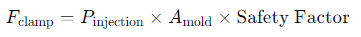
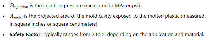
Where:
[elementor-template id=”4330″]
3. Calculation Steps
Step 1: Determine Projected Area of the Mold Cavity (A_mold)
The projected area of the mold cavity is calculated based on the dimensions of the part and its layout in the mold.

Where:
- L is the length of the part in the mold cavity.
- W is the width of the part in the mold cavity.
For complex geometries, the projected area can be calculated using CAD software or mold design specifications.
Step 2: Determine Injection Pressure (P_injection)
The injection pressure can be determined based on the material being used, part design, and process requirements. Typical injection pressures range from 10,000 psi to 30,000 psi (70 MPa to 200 MPa) or higher depending on the material and part geometry.
Step 3: Apply the Safety Factor
Apply a safety factor to ensure the mold remains securely closed during injection. This factor accounts for variations in material properties, process conditions, and safety margins.
Example Calculation
Assume the following parameters for an injection molding project:
- Injection pressure (P_injection): 20,000 psi (approximately 140 MPa)
- Projected area of the mold cavity (A_mold): 100 square inches (645 square centimeters)
- Safety factor: 3
[elementor-template id=”4331″]
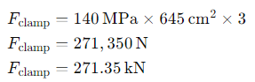
Step 1: Calculate Clamping Force (F_clamp)

Convert the projected area from square inches to square centimeters for consistency:
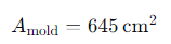
Now calculate clamping force:
Considerations
- Material Properties: The type of plastic material being used affects the required clamping force due to its viscosity, shrinkage, and flow characteristics.
- Mold Design: Complex mold designs or multi-cavity molds may require adjustments to the clamping force calculation.
- Injection Speed: Higher injection speeds may require higher clamping forces to maintain mold closure.
- Safety Margin: Always apply a safety factor to ensure the mold remains closed under all operating conditions.
By calculating clamping force accurately, manufacturers can select the appropriate injection molding machine and ensure that the mold can withstand the pressures exerted during the injection process, resulting in consistent and high-quality molded parts.
Related Conten: https://www.m-dtg.com/service/plastic-injection-molding/
 DTG Mould Trade Process |
|
| Quote: | According to sample, drawing and specific requirement. |
|---|---|
| Discussion | Mold material, cavity number, price, runner, payment, etc. |
| S/C Signature | Approval for all the items. |
| Advance | Pay 50% by T/T |
| Product Design Checking | We check the product design. If some position is not perfect, or can not be done on the mould, we will send customer the report. |
| Mold Processing | Send report to customer once each week |
| Mold Testing | Send trial samples and try-out report to customer for confirmation |
| Mold Modification | According to customer’s feedback. |
| Balance Settlement | 50% by T/T after the customer approved the trial sample and mould quality. |
| Delivery | Delivery by sea or air. The forwarder can be designated by your side. |
 |
|