Two-Shot Injection Mold for Hard-Soft Parts | DTG
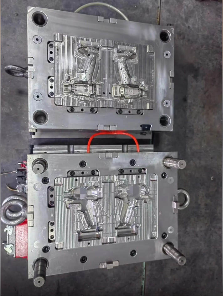
Integrated Hard- and Soft-Material Components
Custom Two-Shot Injection Mold and 2K Injection Mold Solutions
Product teams developing power tools, medical housings, garden equipment, and electronic devices often need rigid structural support and a soft functional surface in one component. Common risks include weak material bonding, flash at the interface, first-shot deformation, inaccurate mold rotation, unstable cooling, gate interference, and inconsistent soft-touch coverage.
DTG TECH CO., LTD. develops each Two-shot Injection Mold around the selected materials, injection sequence, shrinkage difference, machine configuration, interface geometry, and production requirements. This engineering approach helps reduce secondary assembly while supporting stable dimensional, functional, and cosmetic performance.
- ✓Rigid-plastic and elastomer compatibility assessment
- ✓180-degree rotating mold and independent ejection design
- ✓Gate, venting, cooling, shut-off, and pre-compression review
- ✓Support from DFM and mold manufacture to trial and production
Application Scenarios and Customer Requirements
Two-shot plastic molding is suitable when one component must combine different mechanical, tactile, visual, or protective functions without a separate assembly operation.
Power Tool Housings
Rigid housings support internal mechanisms, while soft grip zones improve handling, anti-slip performance, vibration control, and user comfort.
Hand and Garden Tools
Handles and controls require durable material integration, stable surface texture, impact resistance, and repeatable elastomer coverage.
Medical Device Housings
Medical products may require rigid support, soft contact surfaces, controlled interfaces, clean appearance, and reduced secondary assembly.
Consumer Electronics
Hard-hard and hard-soft combinations support color separation, tactile controls, sealing features, shock protection, and brand differentiation.
Two-Color Rigid Parts
Two compatible rigid plastics can be combined to create permanent color separation and integrated visual or functional zones.
High-Volume OEM Programs
Automated transfer or mold rotation reduces manual positioning variation and supports repeatable production across extended order schedules.
What Is Two Shot Injection Molding?
Two-shot injection molding processes two plastic materials or colors on one dedicated molding machine. The materials are injected in two coordinated stages, but the finished component is ejected only after both stages are complete.
A typical Dual-shot Injection Mold operates with two injection units, two molding nozzles, coordinated process controls, and a rotating or indexing mechanism. Depending on machine design, the movable mold section may rotate by 180 degrees or 120 degrees.
- The first material forms the rigid substrate or initial color region.
- The first-shot component remains on the core after the mold opens.
- The core rotates or indexes to the second molding station.
- The second material is injected over or around the first-shot component.
- The completed two-material component is cooled, ejected, and inspected.
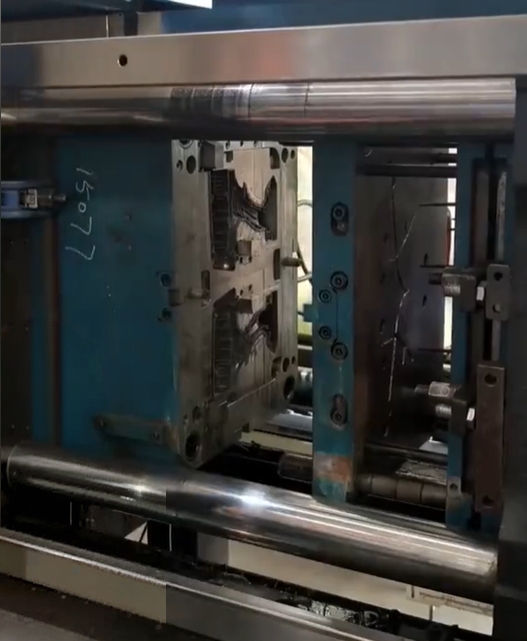
2 Shot Injection Molding vs Overmolding
Both processes combine two materials, but they differ in equipment, part transfer, automation, tooling investment, production speed, and suitability for specific order volumes.
| Evaluation Area | Two-Shot Injection Molding | Conventional Overmolding |
|---|---|---|
| Equipment | Dedicated machine with two injection units and automatic rotation or indexing. | Usually uses separate molds or machines with manual or robotic insert transfer. |
| Part transfer | Completed automatically by mold rotation or indexing. | First-shot components are transferred to another cavity or machine. |
| Automation | Higher automation and lower manual handling variation. | More dependent on loading, transfer, and insert-position control. |
| Tooling cost | Higher initial investment because of complex mold architecture. | Can be lower for prototypes or lower-volume production. |
| Cycle efficiency | Both stages are completed in one coordinated production cycle. | Additional transfer and handling increase total processing time. |
| Best suited for | Stable medium- and high-volume production. | Prototypes, lower volumes, or flexible insert-loading programs. |
Material-Pairing Principles
Material pairing affects adhesion, mold feasibility, shrinkage, dimensional stability, interface sealing, processing temperature, and long-term product performance.
Rigid First, Soft Second
The rigid first shot establishes product geometry and provides stable support for TPU, TPE, or TPR overmolding.
Transparent First
Transparent material is normally molded before opaque material to reduce contamination and preserve the defined visible area.
Higher Temperature First
The higher-processing-temperature resin should generally be molded first to reduce thermal damage during the second stage.
| Material Combination | Configuration | Typical Purpose |
|---|---|---|
| ABS + TPU | Rigid + soft | Structural body with anti-slip or soft-touch coverage |
| PC + TPU | Rigid + soft | Impact-resistant substrate with functional elastomer |
| PC/ABS + TPE | Rigid + soft | Housing with flexible grip and vibration-control zones |
| ABS + PC | Rigid + rigid | Color separation or visual differentiation |
Shrinkage Matching and Dimensional Control
The first-shot material establishes and supports the main product outline. A large shrinkage difference between materials can affect cavity fit, warpage, sealing pressure, interface stress, and the final dimensions of the integrated component.
| Shrinkage Difference | Design Consideration |
|---|---|
| Up to approximately 0.3% | Normally manageable, subject to geometry, wall thickness, adhesion, and process behavior. |
| More than approximately 0.3% | Requires detailed evaluation during DFM and mold design. |
| More than approximately 0.5% | May require more complex support, sealing, interface, or mold architecture. |
Partial and Full Overmolding Architectures
Partial Overmolding
The rigid first-shot part remains on the rotating core, and the second material covers only selected grip, sealing, cushioning, or contact areas.
- Lower soft-material consumption
- Relatively lower mold complexity
- Suitable for local grip or functional zones
- Common for tool housings and handles
Full Overmolding
The second material covers the full rigid substrate using an integrated mold base and rotating movable center plate.
- Complete external soft coverage
- Higher positional and sealing requirements
- More complex mold construction
- Greater second-material consumption
2K Injection Mold Base and Positioning Requirements
Rotation between molding stations places strict requirements on mold-base accuracy, symmetry, plate interchangeability, locating features, machine compatibility, and long-term wear control.
Mold-Base Construction
The source design specifies an S60C high-carbon-steel mold base, Futaba-standard construction, through-bolt fastening, and equal mold-base thickness.
Symmetrical Guidance
Guide pillars, bushings, side locks, and rear-mold features must remain symmetrical after 180-degree rotation.
Machine-Specific Pitch
Product pitch, locating-ring diameter, nozzle positions, screw holes, rotating shaft, and ejector-rod locations must match the selected machine.
Core Interchangeability
Either rear core must match the corresponding front cavity after rotation without interference, height mismatch, or sealing error.
Rotational Clearance
External clamping plates require sufficient C-angle clearance to avoid machine and mold interference during rotation.
Four-Side Referencing
Four-side center-referenced machining supports positional consistency when mold plates are rotated, flipped, or interchanged.
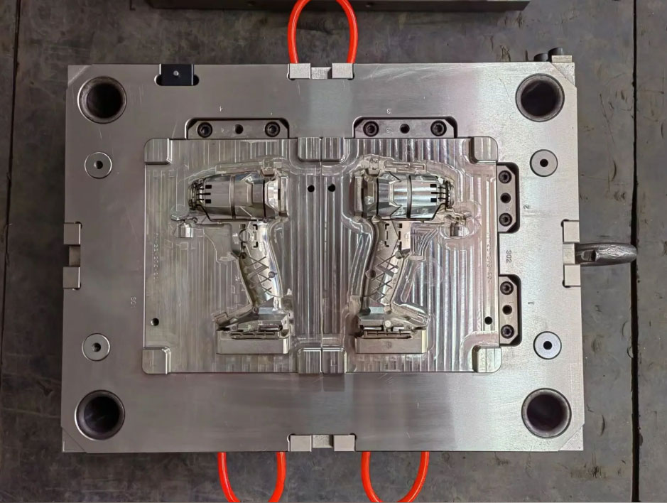
Core, Cavity, and Ejection-System Design
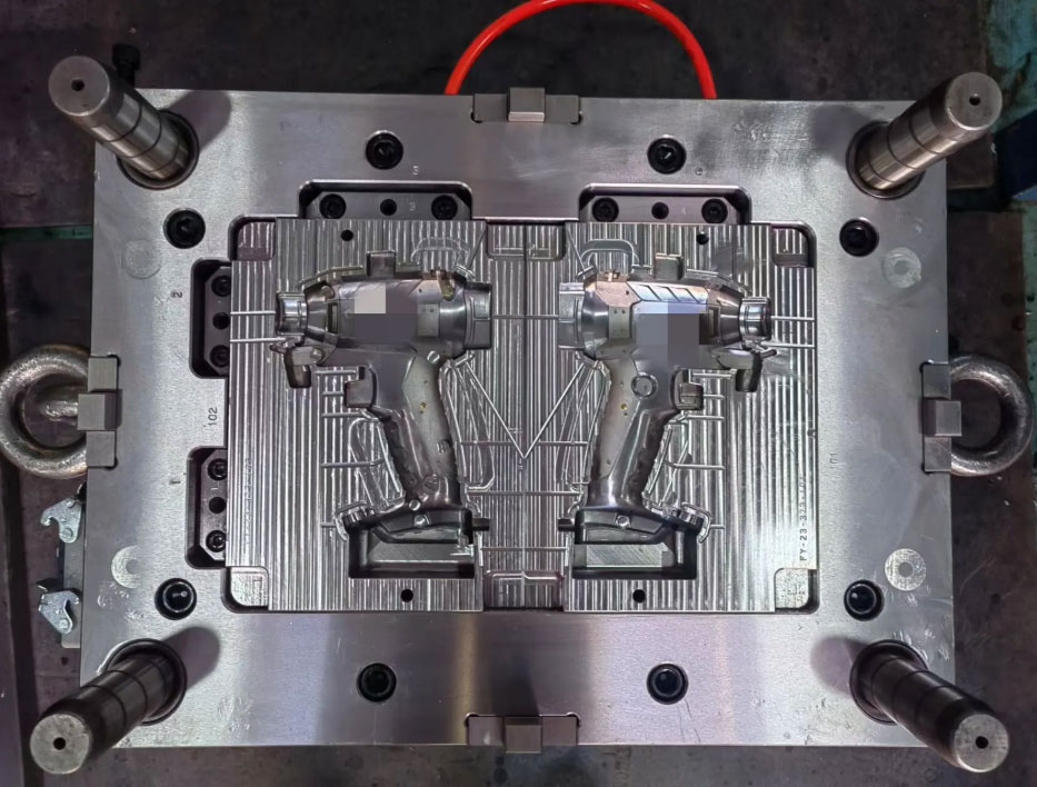
Core and Cavity Relationship
- The two front cavity sides form different molding stages.
- The two rear core sides must have identical geometry.
- The rear mold rotates 180 degrees while the front side remains stationary.
- A rotational alignment and interference check is mandatory.
- Corresponding mold-frame surfaces must remain at matching heights.
Independent Ejection
- Two independent ejection systems and ejector rods are required.
- Ejector layouts must correspond through rotation rather than translation.
- Spring return is required for the rotating rear-mold ejector plates.
- Forced screw return should not be used on the rotating side.
- The complete layout must be verified against the selected molding machine.
Gate and Runner Design
| Design Area | Manufacturing Risk | Recommended Control |
|---|---|---|
| First-shot gate vestige | May prevent correct seating or interfere with the second-shot cavity. | Use an automatically separating submarine gate where feasible. |
| Pin-point first-shot gate | Residual gate material may penetrate the second-shot region. | Add controlled local clearance or consider a three-plate or hot-runner system. |
| Visible second-shot gate | May reduce cosmetic acceptance or require manual finishing. | Use a concealed submarine, cashew, or bottom-overlap gate where suitable. |
| Direct melt impact | May displace, deform, or damage the unsupported first-shot substrate. | Redirect flow, improve part support, and adjust gate position and process conditions. |
Cooling, Operator Access, and Part Removal
Same-Face Water Connections
Each circuit’s inlet and outlet should remain on the same permitted face so hoses do not interfere after mold rotation.
Machine Clearance
Mold height, water fittings, hose routing, rotating mechanisms, machine platens, and operator access must be reviewed together.
Thermal Balance
Uneven cooling can create warpage, shrinkage variation, internal stress, cycle instability, and inconsistent sealing pressure.
First-Shot Position
The first shot should begin on the non-operator side and rotate to the operator side for the second shot and removal.
Automated Clamping
For automated programs, clamping provisions should be arranged on the operator and non-operator sides rather than the top and bottom.
Smooth Removal
Ejection, soft-material release, texture, runner removal, and robot access must be coordinated before production release.
Shut-Off, Interface, and Parting-Line Design
Contact Shut-Offs
Contact shut-offs should be used where possible instead of penetrating shut-offs. Product geometry may be adjusted to provide a stronger and more stable sealing condition.
Parting Surfaces
The rear-mold parting surface should reflect the combined geometry of both stages, while each front-mold parting surface should follow the individual product formed at that station.
Interface Retention
- Textured bonding features
- Sealing grooves
- Mechanical retention geometry
- Controlled contact and penetration shut-offs
- Material-compatible interface design
Critical Dimensional Tolerances
| Feature | Source Tolerance Requirement | Purpose |
|---|---|---|
| Front and rear flanges | −0.05 mm | Supports consistent installation and rotational matching. |
| Distance between flanges | ±0.02 mm | Controls relative station positioning. |
| Ejector rod to ejector hole | 0.10 mm clearance per side | Allows stable ejector movement without excessive play. |
| Guide-pillar and bushing center distance | ±0.01 mm | Maintains alignment after 180-degree rotation. |
| Mold-frame depth | −0.02 mm | Reduces height mismatch and second-shot flash. |
Second-Shot Cavity and Pre-Compression Design
Local Clearance
Controlled clearance can prevent the second cavity from scratching the first-shot surface, but excessive clearance can weaken the shut-off.
Controlled Pre Compression
The source guidance specifies approximately 0.05–0.10 mm of controlled compression to improve second-shot sealing.
First-Shot Support
Thin walls, cosmetic regions, and sealing zones must be supported against second-shot pressure and melt-flow impact.
Flow Direction
Gate position and flow direction should minimize displacement, deformation, local flash, and damage to the first shot.
Slider Sequence
A and B plates should close and support the product before front-mold sliders or lifters return.
Action Verification
The complete closing, rotation, slider, lifter, injection, opening, and ejection sequence must be checked before trial molding.
Pre-Tooling Review
The product layout and mold architecture must be established around the selected two-shot machine before machining begins.
- Product geometry and overmolding coverage
- Material pairing and injection sequence
- Shrinkage and processing-temperature differences
- Mold-rotation direction and angle
- Machine screw holes and clamping positions
- Ejector-rod size and position
- Rotating-shaft size
- Nozzle spacing and X- or Y-axis orientation
- Cooling-water and hose clearance
- Required sliders, lifters, and mold movements
- Machining, inspection, and mold-matching strategy
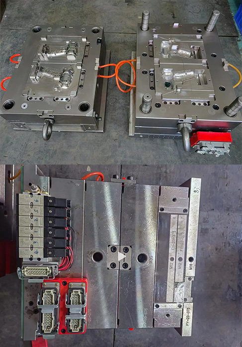
Precision Mold Manufacturing and Matching
CNC Machining
Machine mold plates, inserts, cores, cavities, and mechanism features from defined datums.
WEDM and EDM
Produce detailed shut-offs, openings, profiles, deep geometry, and precision interfaces.
Precision Grinding
Control plate height, matching surfaces, flange dimensions, and rotational correspondence.
Mold-Base Inspection
Reject mold bases that do not meet the specified dimensional and positional tolerances.
Rotational Matching
Match the first cavity with both cores, then match the second cavity to a verified core.
Mold Installation and Trial-Molding Controls
Remove all mold-locking screws and verify free movement before installation.
Install the complete first-shot mold on the non-operator side.
Insert all clamping screws by hand before final tightening.
Open the mold and rotate the rear core side by 180 degrees.
Use the verified first core and second cavity as installation references.
Apply final machine adjustment only after both mold sets are secured correctly.
Soft-Material Processing and Venting
TPU and TPE have high flowability, making mold-fit accuracy, shut-off support, vent cleanliness, interface compression, and process settings particularly important during the second shot.
| Venting Area | Source Vent-Depth Guidance | Primary Risk Controlled |
|---|---|---|
| General soft-material sealing area | Within approximately 0.015 mm | Flash while releasing trapped gas |
| First- and second-shot interface | Approximately 0.03–0.06 mm | Air traps, burns, incomplete filling, and interface defects |
Final vent dimensions must be validated against the actual resin, cavity pressure, steel condition, texture, interface location, and trial results.
Common Production Issues & Solutions
| Common Production Issue | Possible Cause | Recommended Solution |
|---|---|---|
| Second-shot flash | Weak shut-off, excessive clearance, first-shot deformation, or excessive local pressure. | Improve sealing surfaces, reinforce support, adjust clearance, and optimize injection conditions. |
| Trapped air | Insufficient venting at the interface or end-of-fill region. | Add or optimize vents within the validated depth range. |
| First-shot compression damage | Excessive pre-compression or premature slider and lifter return. | Correct the compression allowance and revise the mold-action sequence. |
| First-shot deformation | Second-shot flow impacts an unsupported wall or sealing region. | Improve support, redirect flow, revise the gate, or reinforce the product locally. |
| Gate interference | The first-shot gate vestige protrudes into the second-shot cavity. | Use automatic gate separation or provide controlled local clearance. |
| Misalignment after rotation | Mold-base, guide, flange, or frame tolerances are inconsistent. | Reinspect rotational geometry and correct the affected components. |
| Soft material sticking | The elastomer adheres strongly to an overly smooth mold surface. | Retain suitable texture and review draft, temperature, cooling, and ejection. |
| Poor material integration | Incompatible materials, contamination, low interface temperature, or inadequate retention. | Review compatibility and add texture, grooves, or mechanical interlocks where required. |
| Cooling interference | Water circuits and hoses are not arranged for mold rotation. | Place each circuit’s inlet and outlet on the same approved mold face. |
Quality Control and Inspection
| Inspection Item | Verification Scope |
|---|---|
| Coordinate Measuring Machine Inspection | Full-dimensional verification of mold components and critical interfaces. |
| Optical Measurement | Planar dimensions, feature position, spacing, and profile accuracy. |
| Rotational Fit Accuracy | Alignment after the mold-base sets are rotated and interchanged. |
| Shut-Off Verification | Contact, penetration, sealing strength, and flash-control performance. |
| Trial-Molding Validation | Part dimensions, appearance, material integration, ejection, rotation, and actual production behavior. |
Mass-Production Consistency
Repeatable output depends on the stability of the complete molding system rather than any single mold component.
Development Schedule and Manufacturing Capability
Actual schedules and tool performance depend on part size, material, mold structure, machine configuration, complexity, approval cycles, production conditions, and maintenance.
Technical Advantages of Two-Shot Molding
Reduced Secondary Processing
Two materials are formed in one integrated molding process, reducing separate assembly, adhesive application, fixtures, and handling.
Higher Interface Strength
Compatible materials can bond through molten-state interaction and can be reinforced with mechanical retention geometry.
Improved Repeatability
Automated mold rotation reduces manual positioning variation between the first and second material stages.
Greater Design Flexibility
The process supports rigid-rigid, rigid-soft, two-color, tactile, sealing, impact, and appearance functions.
Reduced Assembly Gaps
Direct integration in the mold eliminates many seams associated with separately assembled parts.
Material-Cost Options
Recycled secondary material may be evaluated for internal core regions where product requirements permit.
DTG Project Workflow
Review files, materials, machine data, annual volume, inspection requirements, and delivery targets.
Confirm technical scope, commercial terms, tooling responsibilities, and project milestones.
Begin engineering and material preparation after receipt of the agreed 50% advance payment.
Complete DFM, material, shrinkage, rotation, gate, cooling, venting, ejection, and action analysis.
Manufacture and inspect the tool while providing scheduled project-progress reports.
Run trials and provide samples with dimensional, functional, and visual observations.
Implement agreed adjustments based on sample inspection and customer feedback.
Complete the remaining 50% payment after sample approval under the agreed terms.
Complete final verification, packing, documentation, and shipment by the selected method.
Engineering Summary
A Two-shot Injection Mold must coordinate two materials, two injection stages, different cavity conditions, independent ejector systems, and a rotating rear mold within one controlled production cycle.
The main challenge is not the basic concept. Reliable production depends on material compatibility, shrinkage matching, mold-base accuracy, 180-degree alignment, gate separation, cooling routing, second-shot clearance, controlled pre-compression, shut-off strength, vent depth, slider timing, and first-shot support.
DTG combines DFM, machine-specific mold design, precision manufacture, controlled fitting, structured trial molding, dimensional verification, and production support to establish a stable process for integrated hard- and soft-material components.
Frequently Asked Engineering Questions
What is the correct material sequence for hard-soft molding?
The rigid material should generally be molded first, followed by the soft material. This provides stable support for the second shot.
Can the second-shot material use a higher processing temperature?
The second-shot temperature must remain within a range that does not soften, deform, remelt, or otherwise damage the first-shot substrate.
How is second-shot flash controlled?
Flash control depends on shut-off strength, mold matching, pre-compression, first-shot support, vent dimensions, local clearance, and injection pressure.
What files are required for quotation?
Recommended inputs include 2D drawings, 3D data, resin specifications, machine information, annual volume, mold-life target, surface requirements, inspection criteria, and delivery destination.
What is the expected mold-development schedule?
The source guidance indicates approximately 5–7 days for mold design and approximately 35–45 days for mold manufacture and trials, subject to complexity and approval time.
Start a Two-Shot Mold DFM Review
Send your 2D drawings, 3D files, material requirements, overmold coverage, machine information, annual volume, test criteria, and target delivery schedule. DTG will review material compatibility, shrinkage, rotational layout, gate position, cooling, venting, ejection, sealing, pre-compression, and tooling feasibility.
Ready To Start Your Project?
Tell us about your part, material, quantity, or mold requirements. Our team will review your project and provide a practical manufacturing solution.